Cvt Transformer Circuit Diagram High Voltage Transformer Cir
Difference between capacitive voltage transformer cvt and ccvt: Cvt-constant voltage transformer-working, circuit diagram, application Transformer voltage capacitor ccvt coupling cvt
Capacitive Voltage Transformer (CVT) : Working & Its Phasor Diagram
Capacitor cvt transformer Capacitive voltage transformers (cvt) Cvt transmission diagram
Capacitor voltage transformer (cvt or ccvt)
Schematic diagram of cvt mechanismWhat is cvt Cvt in electrical- circuit diagram, construction and working ofCvt mechanism.
Pros and cons of the cvt transmissionTransformer voltage transformers capacitor capacitive cvt What is cvt transmission? diagram, parts, working, advantagesPotential transformer circuit diagram.

Transformer capacitor cvt ccvt
Dólar senado aplicable voltage transformer substation empleado canberraTransformer circuit working principle works electrical gif fig each electricalacademia Cvt transmission honda car automatic variable cars between difference accord use many vvt gearbox gear parts cons pros audi subaruWhat is constant voltage transformer (cvt)? working principle, diagram.
Capacitive cvt circuitSchematic of cvt powertrain subsystems. Difference between capacitive voltage transformer cvt and ccvt:Instrument transformer cvt transformer.

Capacitive voltage transformer (cvt) : working & its phasor diagram
What is constant voltage transformer (cvt)? working principle, diagramEquivalent circuit of transformer referred to primary and secondary Variable cvt transmission continuously automatic works pulley difference between car diameter picture speed high chain torque sprocket secondaryCvt transformer.
Transformer cvt voltage capacitive capacitor between transformers diagram circuit kv phase connected earth line therefore will power different electricityTransformer circuit equivalent primary secondary phasor side referred parameters voltage electrical resistance form determination fig ratio reactance electricalacademia Cvt subsystems powertrainVoltage transformer capacitor capacitive cvt.

Voltage capacitor transformer cvt construction ccvt high working electrical
Constant voltage transformer (cvt) how does it workConstant voltage transformer (cvt) High voltage transformer circuit diagramCvt in electrical- circuit diagram, construction and working of.
Capacitor voltage transformer (cvt or ccvt)Cvt supply power constant voltage transformer Capacitor coupled voltage transformer (cvt or ccvt)Transformer voltage constant cvt circuit diagram working application.

Difference between current transformer and potential transformer
Transformer potential diagram circuit current difference between electrical transformers gif fig find androidTransformer working principle Cvt in electrical- circuit diagram, construction and working ofElectrical schematic diagram of cvt. cvt is employed for testing.
Cvt or ccvt(coupling capacitor voltage transformer)Cvt-constant voltage transformer-working, circuit diagram, application High voltage transformer circuit diagramCapacitive voltage transformer (cvt) : working & its phasor diagram.


Constant Voltage Transformer (CVT) How Does It Work | Transformer

Capacitive Voltage Transformer (CVT) : Working & Its Phasor Diagram

Difference between Current Transformer and Potential Transformer
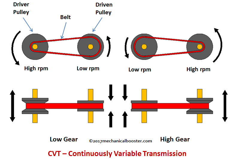
What is CVT - Continuously Variable Transmission and How it Works

CVT-Constant Voltage Transformer-Working, Circuit Diagram, Application

Electrical schematic diagram of CVT. CVT is employed for testing

CVT or CCVT(Coupling Capacitor Voltage Transformer) - YouTube